
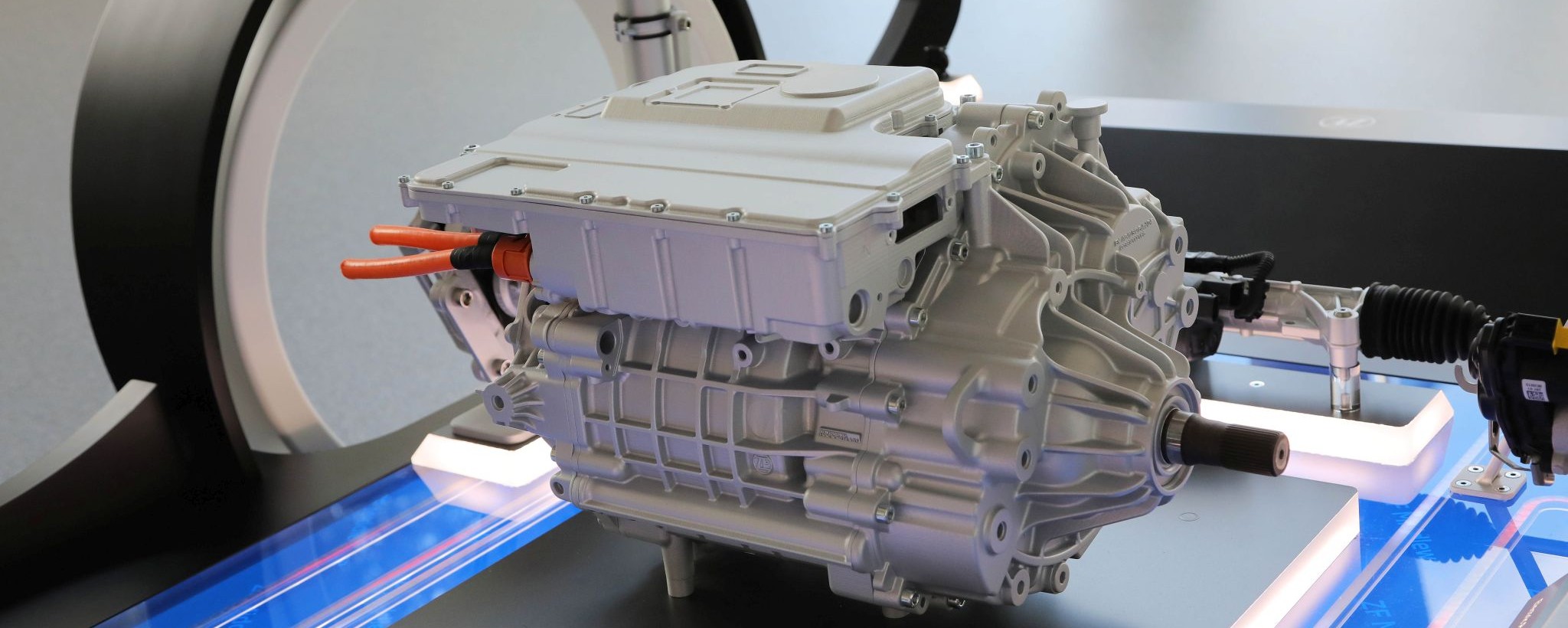

Power electronics: The control center in the electric drive
However, these dynamics also sometimes give engineers a headache – especially when it comes to combining this dynamic handling with efficient energy use. A key concern for ZF developers. Here, the power electronics come into play as the central switching point for the electric drive: Functionally arranged in the driveline between the battery and the electric motor, this aluminum housing measures around 30 by 30 centimeters. One task of the power electronics is to convert the direct current from the battery into alternating current for use in the electric motor. Hence, this part of the power electronics is called the inverter. Put simply, here you have several transistors that switch on and off at extremely short, regular intervals. When switched on, they transfer the battery current to the motor. Together, these high-frequency switching operations produce a sinusoidal voltage curve which provides the ideal traction energy for the electric motor.

The power electronics transfer the traction energy from the battery to the electric motor, converting that energy from direct to alternating current. ZF software varies the frequency without compromising efficiency, comfort, NVH behavior or the battery's service life.